Please excuse my bad English, I am native Italian, living in Germany.
I am not keeping this "Ford-style" with all the warnings and stuff so if you hurt yourself or set your Mark on fire please don't blame me. It worked for me and should work for all 1st gen's, but as mine is the only Mark I ever worked on I take no guarantees. First, find yourself the necessary tools, screwdriver, paperclip, a knife and a soldering iron. You might want to disconnect your battery although I left mine connected. Just make sure the autolamp is off and headlights are off. First, turn the key to "RUN" and remove the lock cylinder. This is done by creeping under the steering column and pushing a paperclip up a small hole in the lower steering column cover to unlock the cylinder. You can then just pull it out, provided it is in "RUN" position. This will keep the ignition on during the whole process so if you don't have a fully charged Optima like I do this is the time to reconsider disconnecting the battery... Unscrew the steering wheel tilt lever and put it out of the way. Then, remove both steering column covers, upper and lower part, they are snapped together in addition to being held by four screws. One of the screws sits on the lower right inside and is hard to locate. Don't use any brute force, they should come right apart.
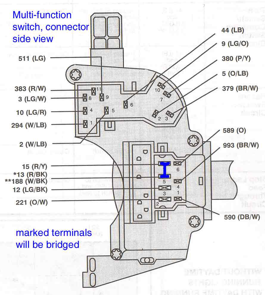
This will enable you to see the multifunction switch which itself is held by two screws (Torx bit size 20 if I remember right). You will also eventually see two thin yellow interesting little wires - these are for the air bag and you should resist the temptation to touch them. Remove the two screws and take off the multifunction switch assembly consisting of the turn signal lever and the hazard switch. It has two connectors shown in picture2 (attached) which must be pulled off. Take care not to break the little clamps securing them in place. Ignore the larger connector and take a closer look at the small one. It has a red plastic insert which can be removed by carefully prying away the tiny clips it has holding it in place.
After removing the red thingy you can pull out the individual connectors by prying away the tiny grey tongues securing them then pulling on the wires - again, the paperclip (Rotunda tool #93289-398872-1220) comes in handy. You need to pull the two upper left hand connectors marked in picture2. These are wire numbers 15 and 13, red with yellow and red with black.
You can now prepare a piece of automotive grade wire about two inches long and solder it to both of the connectors, thus bridging the wires 15 and 13. Be careful not to use too thick a wire or you won't get the connectors back into their housing. You best solder it on the upper end of the connectors.
Let everything cool down and put the connectors back into their housing by pushing them in until the tiny grey tongues snap into place. Be careful not to reverse the connectors or the tongues won't snap, allowing the connectors to be pushed out of the housing. Double-check for copper strands coming out of the plastic connector housing as they could cause shorts, blown fuses or fire. (or all three) In case of fire, I will buy your engine for a good price ;-)
Put the red clamp thing back into place until it snaps in.
Replace both connectors on the multifunction switch.
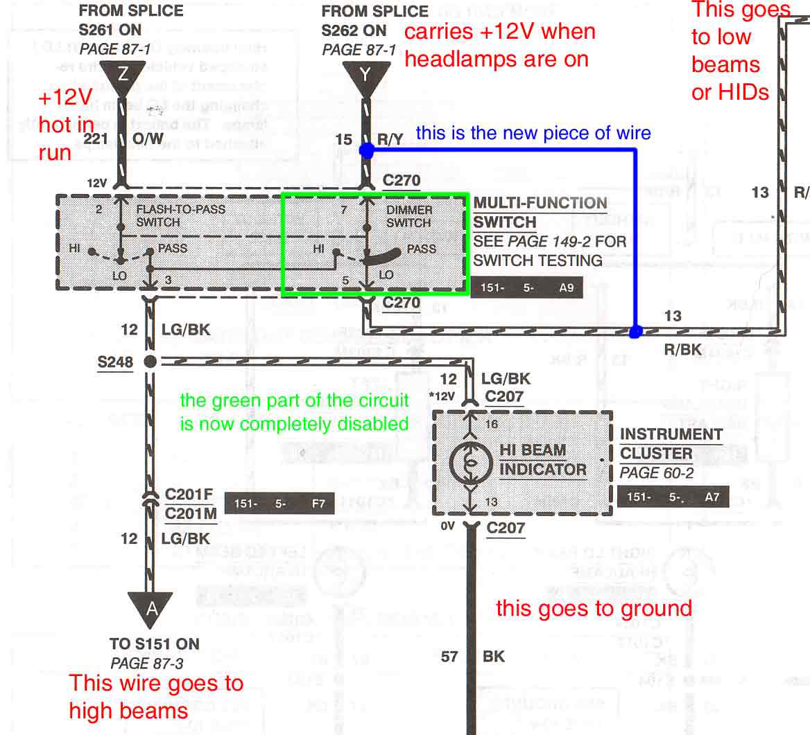
After that, you can verify the operation of your headlamps if you feel like it. I was very self-confident and put everything back together before I tried it. Screw the switch assembly back on taking care of the wires - they must not interfere with the tilt column mechanism. Put the steering column covers back on, screw in the tilt column lever, and put the ingition lock cylinder back in. Turn the ignition off and verify correct operation of the ignition lock. If you disconnected your battery before, reconnect it now and you're done. This job took me about twenty minutes. It took me more time to write this here novel and scan the pictures. For the electrical part of the story, you find a documented schematic of the HI/LO beam part of the multifunction switch in picture1. So you see, there is no additional current to be handled by this or any other switch, no wires to be cut, no relays and no problem in restoring the original condition - just snap the wire you installed before. All we did is bypass the lo-beam side (marked green) of the multifunction switch, making lo beam being controlled only by the light switch. This is not rocket science after all, just a simple idea. If it helps anyone I am glad to be of assistance.
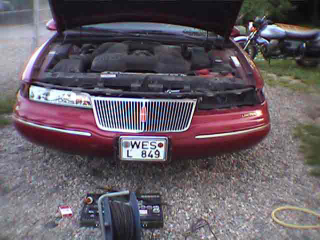
Attached are three jpegs, one of them shows my one-eyed Mark waiting for the headlight installation to be completed. Hope my description of the process is not too long, but I do this everyday - I build computer networks and every other day customers call me to help them with some problem and then it's "move the mouse on the OK button, press the left mouse button, then move to device manager, then..." sometimes for an hour or so. Q:"Tell me exactly what it says on the first line on your monitor" A:"T-R-I-N-I-T-R-O-N" Please feel free to rewrite this, change it or do whatever you feel like with it.
best regards Abel.
Abel W. A. Cerrone Stehfest [abel@its-technologies.com]