Reserve Tank System Update Page

Overview


This page briefly explains how to upgrade the existing Mark VIII air suspension to a manually adjustable fast bag system. I have included a list of components that you will need as well as some special modifications required to install this system. I do not go into how the system works or how to install everything. This page just gives an overview of what is involved. I hope to have more information available soon. Below are some things I am currently working on and some videos of the system in action. Feel free to email me with any questions.

List Of Components

Some of these items can be swapped with different and/or better parts. For example, you may want to go with a single 6 gallon tank or bigger valves and lines. I recommend a minimum of 1 compressor for every 4 gallons of air reserves. I run 1 compressor for every 2.5 gallons of air and it takes less than a minute to go from 110-145psi. I have also left out any relays, diodes and wiring required for remote operation via the alarm system.
8 - SMC VXD2130 3/8" Solenoid Valves
1 - Thomas 315 Compressor
1 - Mark VIII Compressor
1 - 4 Gallon Tank
1 - 1 Gallon, 5 port tank
1 - 110/145psi Pressure Switch
1 - Check Valve
1 - Water Separator
1 - Air Dryer
1 - Fuse Block and High Amperage Fuses
1 - High Amp Battery fuse
1 - 40 Amp Automotive Relays
2 - 30 Amp Automotive Relay

2 - Ball Valves
2 - Needle Valves
1 - Petcock Valve
4 - On-Off-On Momentary Switches
80 Feet 1/2" Nylon Tubing
20 Feet 3/8" Nylon Tubing
100 Feet 16ga. Power Wire
50 Feet 16 ga. Ground Wire
25 Feet 4 Gauge Power Wire
20 Feet 10ga Power Wire
20 Feet 10 ga Ground Wire
Misc. Electrical Connectors
Misc. Push To Connect and Pipe Thread Fittings


Special Modifications

FRONT STRUTS:

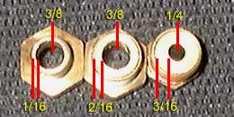
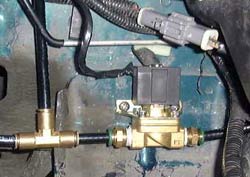
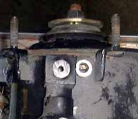
To be able to lift the car quickly, you need to enlarge the diameter of the hole where the airline connects. Simply attaching a bigger line will not make the system faster. Below is a comparison between the stock size and the enlarged size as well as the stock configuration and modified strut with airline attached. Using a hacksaw, I was able to hack off the stock solenoid mounting bracket and drill a 5/16" hole in the leftover material. Next I bought a 1/8" NPT tap and threaded the hole to accept an1/8" NPT fitting. I also drilled a 7/16" hole in the body of the strut and tapped it to accept a 1/4" NPT fitting.
 
Stock Strut and Solenoid Hole Comparison Modified Strut  

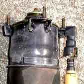
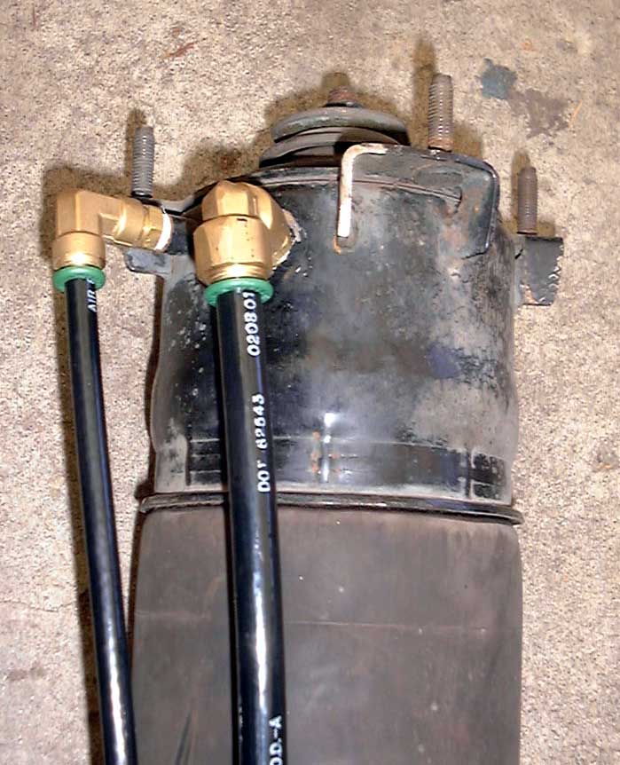
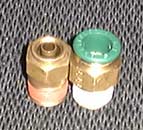
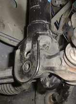
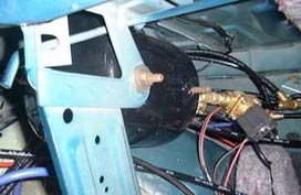
The finished strut uses a 1/2" suppy line and a 3/8" dump line. You can click the leftmost pic for a close up. Depending on where you drill on the base of the strut and what fittings you decide to use, you may or may not have clearance problems when you install the strut. The fittings are located towards the engine compartment which could make it difficult to install the lines once the strut is in place. The other option is to cap the stock solenoid hole and drill the new holes on the outermost side of the strut (away from the engine compartment). You have to take into consideration the travel of the control arm/steering knuckle if you do so.

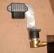
The other problem I ran into was that the fitting would not screw in because part of the strut was in the way. To solve this, I ground down a portion of the strut, then finally switched to a different fitting. Some fittings will swivel which will allow you to screw in a 90 degree elbow in a tight spot. These are the fittings that may be a tight fit since they protrude more than the others.

REAR BAGS:

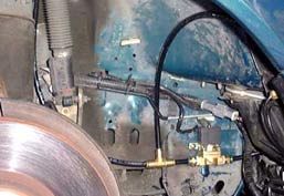
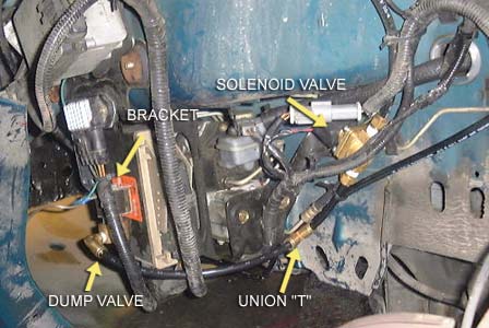
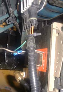
The rear was similar to the fronts except they were much easier. I didn't even have to remove the bags from the car. I used the same drill bit (7/16") and drilled directly into the plastic mounting base of the bag. If you are using a 90 degree fitting like the one pictured, make sure you have enough clearance to thread the fitting into the bag, there is a plate that the body of the fittings will hit if you drill the hole too close to the top of the bag. You can also use different fittings which swivel. I didn't find these until later. I kept the stock solenoid mounted in place and I have not yet had a problem with the rear bags leaking.
FAR LEFT:
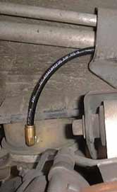
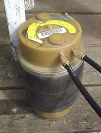
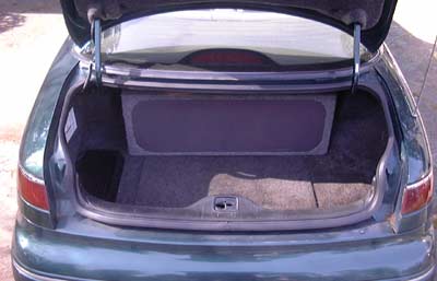
A picture of the 3/8" hose leading to the rear airbag. The stock solenoid can be left in place.

LEFT:
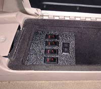
Just in case you decide you want maximum speed, you have the option of drilling multiple holes in the bags or larger holes altogether (see below)

BELOW:
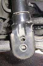
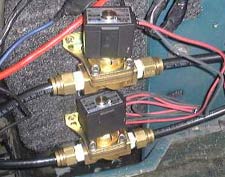
The first two pictures show the front struts threaded to accept 1/4" fittings and 1/2" line instead of the miniture 1/8" fittings. If speed is what you need, you can run two 1/2" valves and Nitrogen. The next two pictures show what I tried to do to get an additional inch of lowering out of the front struts. I made the hole too high and it didn't work out as you can see from the pics. I estimate a 1/2" drop would be possible.

SPECIAL NOTE ABOUT FITTINGS:
You also need to be cautious of how much the fittings neck down. The picture directly to the right shows how there can be differences in the actual orifice size. NON-DOT fittings usually have bigger orifices since they do not have a collar. Two of these fittings were drilled to enlarge the orifice size. The one on the right has not been drilled. You will not be able to find a fitting with only 1/16" wall thickness.

The picture on the far right shows a 3/8" DOT fitting and a 1/2" NON DOT fitting. Notice the collar on the smaller fitting. The DOT fittings are approved by the Department of Transportation for use on Air Brake equipped trucks.

MISC

EXPERIMENTAL:

     In the two pictures on the left, I tried to locate the strut mount higher therefore lowering the vehicle. I made one attempt at it and I overshot it by about a half inch. It could be done, but a special plate would have to be welded to the strut to reinforce the mounting location since you would essentially have one elongated hole. No need for any of that nonsense as there are some killer projects in the works. Eddie Spinks, aka BLUECOLLAR, is working on a custom strut just for this application and we hope to be able to unveil it soon.

INSTALLATION PICTURES:

Below are some misc. pictures that I took while installing the system. The small 1 gallon tank is mounted in an area of the trunk that allows the stock carpeting to conceal it's location. All components are hidden by the factory carpeting and the pumps are mounted inside the spare wheel well. I have two 10" woofers in a speaker box that runs across the rear of the trunk. The box hides the 4 gallon tank and associated hoses coming from the trunk floor. These pics ahow 3/8" lines which is what I was running at first. I now run 1/2" front and rear with dual ports on the fronts. (this eliminates the need for a union T on the front valves.)

Air-Ride control switches - Tank mounted in spare area of trunk - Rear dump valves mounted in trunk

  
Passenger side front inflate valves - Close-up of front inflate valves - Bracket to hold dump valve


Driver side valve placemet - Close-up of the dump valve mounted on custom bracket.

Both sides use the stock relay mounting brackets to anchor the dump valves. The driver side inflate valve is mounted at an angle to make it easier to install/uninstall air hose.
Here is a shot of how much available trunk space you will have if you position the tank ahead of an existing speaker box. The rear dump valves are mounted on a panel on the left side of the trunk behind the carpeting and the inflate valves are mounted directly to the 1 gallon tank. The small tank was able to fit behind the carpeting as well in an area of the trunk above the wheel well. I would like to add a larger tank on each side and get rid of the tank in front of the speaker box. This would give me additional room in the trunk for storage. As you can see, everything looks stock from the outside. I am working on a special housing for the pumps. Stay tuned for pics of the custom enclosure.

Theses two pictures show how much travel you have between extreme high and low. Fully inflated the front measures 30.5" from the ground to the wheel well and 24" slammed. The rear will reach 30.5" as well but will drop about an inch lower to 22 3/4". The height will vary a bit depending on wheel/tire selection but the amount of travel will be the same, roughly 6". I run 245 50 ZR 16s all around on stock 16x7 wheels.


VIDEOS

Windows Media Player:

These are the newest vids showing how fast the 1/2" lines are:

1/2" fronts
- 1/2" rear - 1/2" wideangle


MISC videos documenting the evolution of the system.

Video 1 (661K) - Video 2 (655K) - Video 3 (411K) - Airline Removal(236K)

VIDEO1: SET-UP: 6 valves - 4 SMCs for fill and two small Snap Tite (3/32" orifice) valves for dump.

The front and rear were set up to raise for one second each. The rear goes way too high if not slowed down. The front goes too high as well. The car was also timed to dump for six seconds. The second portion of this video shows the whole car raising off a one-second pulse. The rear still was a bit fast and goes a little high. I installed a ball vavlve on each bag to slow it down. Dump was set for three seconds.

VIDEO2: SET-UP: 8 valves - 4 SMCz for fill, 2 SMCs rear dump, 2 Snap Tites for front dumps.

I use the manual switches to lift the front, then the rear to ride height. It just takes a fraction of a second to reach ride height. I then dump the car via the switches. The second portion of this clip is the same as the first portion of video 1.


VIDEO3: SET-UP: 1 SMC valve running from the tank in the trunk to the passenger side front strut.


For a while the system was running off the stock ECU, this video shows the car raising to ride height with a single 3/8" airline supplying the passenger side front strut only. This was taped right after modifying the strut and installing it on the car. When the rest of the system was thrown into the mix, rise time was much slower.

AIRLINE REMOVAL: Shows removal and installation of the airline from the dryer.


REAL Player:

Video 1 (616K)
- Video 2 (234K) - Video 3(49K)

VIDEO1: An example of a normal day with the system. I raise the car with the alarm button, drive off and return. As I arrive, I drop the car back down to the ground. I then get out and do it all over again from my transmitter while I grab a closer angle.

VIDEO2: Same as above except only the close-up portion.

VIDEO3: Same as Video 3 above.