OVERVIEW
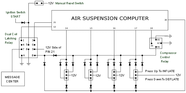
Pictured below is a schematic of the modifications necessary to implement manual
control over the stock air ride system on 93-98 Lincoln Mark VIIIs. It is a simple
network of relays, diodes and switches that energizes the various solenoids to
control ride height. When the system is activated, the stock air ride system is
disabled until the car is either restarted, or the manual reset switch is depressed.
It is importatnt to note that without a diode at the ignition switch, the starter
will be energized whenever the manual reset switch is depressed. All parts are
readily available at your local Radio Shack, except for the latching relay. The
one I used was an ECG Electronics Dual Coil Latching Relay P/N RLY7942D. You can
find them at your local electronics store, or order one online.
click picture for larger printable schematic.
RAISING THE CAR
In order to raise the car you need two things:
1) The compressor has to be running.
2) A bag solenoid has to be open.
The suspension ECU controls the compressor by grounding PIN 18. PINS 14,15,16
and 17 are energized to open the bag solenoids. With the compressor running and
a bag solenoid open, air flows into the bag therefore raising the vehicle.
The logic behind raising the car is simple: When 12v is applied to the bag solenoid,
the compressor control relay starts the compressor, the check air ride message
is disconnected and power to the ECU is cut to allow you to revert back to the
stock system.
To control the system, there are four three-way momentary switches that raise
or lower each corner. When one of the switches is pressed up, current flows from
the 12v terminal of the switch to the inflate circuit. This applies 12V to the
bag solenoid, terminal 86 on the compressor control relay, as well as terminal
B on the latching relay. Voltage at the 86 terminal switches the relay contacts
and grounds pin 18 on the suspension ECU, which in turn grounds the stock compressor
relay causing the compressor to run. Note that there is a relay controlling a
relay. The actual compressor relay is a solid state relay with cooling fins mounted
on it to disperse heat. It is located on the compressor bracket assembly. A diode
prevents the vent solenoid from opening and diodes at each switch allow them to
operate individually (they would share a common contact without the diodes, essentially
connecting the four switches). With the solenoids open and the compressor running,
air goes into the bags and the car raises.
Voltage at the B terminal causes the relay contacts to switch and remained switched
until pin 5 is energized. This will be done automatically when the car is restarted
or can be done manually via a manual reset switch. This temporarily cuts power
to the ECU and the message center lead. Power to the module is cut because the
module will error if left on. Pin 12 is cut in order to prevent the "Air
Ride Off" message from being displayed. In order to bring the stock system
back online, it is essential that the system operate without errors. It is also
important to kill power to the module to prevent the system from correcting any
changes you made to the vehicle trim height.
LOWERING
In order to lower the car you need two things:
1) A bag solenoid has to be open.
2) The vent solenoid has to be open.
Air will always go from an area of high pressure to an area of low pressure. Opening
the bag solenoid allows air to escape the bag and "equalize" with the
lines and dryer. Opening the vent solenoid allows air to escape entirely. The
control module does this by energizing pins 14,15,16,17 and pin 30 for vent control.
Pressing one of the switches down is very similar to pressing it up. With voltage
at terminal B on the latching relay, power is cut to the control module and the
message center lead is disabled. Depending on which switch was depressed, a bag
solenoid opens and air escapes the bag. Additionally, the vent solenoid is opened
allowing air to escape out of the system. This will cause the car to drop. Just
as in the raising circuit, diodes prevent the compressor relay from receiving
this voltage, as well as the other switches.
