Like most automatic transmission equipped cars on the road today, the Mark VIII uses a transmission oil cooler. This OEM cooler is build into the motor's water radiator. It is designed to keep the transmission oil as cool as the motor water temperature. There is no excuse for injecting heat into a cool transmission just because the motor is running hot. Also, when racing or under high speed loads, the transmissions in the Mark can use all the help it can get to remove waste heat. The installation of a separate transmission cooler, with the OEM cooler completely bypassed, has always been a well discussed topic on the Mark VIII forums.
Recently, Maples 8 and I have been swapping email about cooler installation. Having thought out the process and actually already doing it himself, Maples 8 supplied pictures on the install as he did it. Following his lead, I also installed a cooler. The location and the mounting of the cooler is very well thought out. My install went so well, that I though we should share it with the rest of the members in the LOD club.
The following picture of Maples 8's installed cooler is a bug's eye view, just prior to getting terminal headache number 999.
The Cooler: Scanning the discussion forums about transmission coolers, one quickly can see that the cooler to purchase is the "plate type" cooler and not the "fin type." A plate cooler is build like a miniature water radiator. The fin cooler is a long pipe with fins attached to it. Sometimes the long pipe is folded into a loop to reduce overall length and to keep the input and output ports on one side of the cooler.
The cooler we both used were supplied by Carparts.com. It is a 24,000 GVW rated, plate type unit, part number 70264. Once I received it, it turned out to be a B&M "Super Cooler." It comes complete with install hardware kit and decal (B&M Racing Products.). I looked around at several local auto stores, comparing pricing and quality of other coolers. The closest I came to a match was a plate cooler from O'Rielly that sold for 20 bucks more than what I did pay at Carparts.com. The hardware kit supplied with the cooler is designed to be installed in series with your existing radiator cooler. That is, the output of one cooler is routed to the input of the new cooler. Once again, based on forum discussion with members, we bypassed the OEM cooler and allowed the "Super Cooler" to do it all.
Tools needed:
1. Standard blade screwdriver or ¼ inch driver and sockets (for hose clamps.)
2. Drill motor and a selection of metal drill bits (to make pilot holes for mounting straps that hang the cooler.)
3. Mini pipe cutter (to cut existing cooler plumbing.)
4. Sharp knife (to cut cooler hose.)
5. Metal punch (to mark hole to be drilled.)
6. Small screwdriver (to extract plastic rivets.)
7. Standard Phillips head screwdriver (to extract plastic rivets)
8. 13mm tubing wrench (to disconnect existing coolant plumping
9. A small plastic bowl or container to catch tube fluid.
Supplies and Parts needed:
1. Plate type transmission cooler, 24,000 pound GVW rating or above.
2. Three cooler mounting straps (may be in hardware kit for cooler.)
3. Six ½ inch diameter hose clamps (4 clamps may be in hardware kit for cooler.)
4. Three feet transmission oil hose (may be in hardware kit for cooler.) Hose MUST be rated for oil/fuel use.
5. Three sheet metal bolts that fit mounting strap (may be in hardware kit for cooler.) The self-drilling type makes the install go faster and having to drill pilot holes is eliminated.
6. Five nuts, bolts and lock washers for mounting the cooler to the straps (four sets of hardware may be in hardware kit for cooler.)
7. Teflon tape and bolts to plug old radiator cooler lines (optional)
The Install:
1. The cooler is installed on the passenger's of the hood latch, between the air conditioner condenser and the bumper cover frame. This location can be accessed from the top of the engine compartment. To get to the location, you must remove the plastic cover that hides this valuable space.
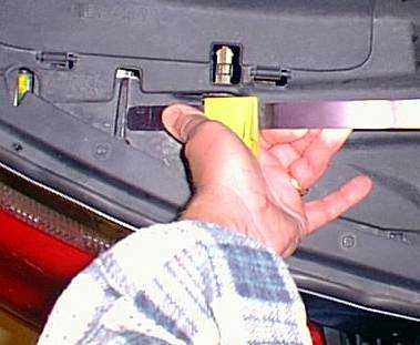
a. The following two pictures show how to remove the safety latch lever. The picture below shows Maples 8 bending the metal "release" lever slightly to allow him to remove the left end of the lever from where it is fitted into a slot in the plastic cover.
b. The next picture below shows how he rotated the lever up to remove the other end from the slotted release mechanism. Set this lever aside. Now attack the plastic cover.
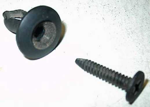
c. The cover is held with 5 plastic, screw expanded rivets. A close up of the head of one of these rivets is shown below.
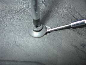
Notice the Phillips screw. If you're very, very lucky, you can turn this screw and it will back out. Once the screw is out, the plastic "rivet" is easily removed from the hole. If you are not so lucky, like 99.99% of the time, you can turn the screw until you puke and die and it will not budge an inch. The secret to getting the screw out is sideways pressure on the rivet bellows. Insert a small screwdriver under the rivet head and press against the internal body as shown in the picture below. You are pressing in on the axis of the rivet. You are NOT trying to pry up on the rivet The screwdriver blade will put pressure on the screw body or on the plastic bellows that the screw enters. Either way, the screw will now creep upward as you turn it to extract it, so long as you keep the pressure on the body. When the head gets far enough up for you to grab it, you can pull the screw out. After removing a few of the rivets, you will be an expert. The following picture shows a rivet removed and taken apart.
d. Once the five rivets are out, lift up on the engine side of the plastic cover. It is fitted into slots at the front edge. Put the cover aside.
2. The space exposed is the space on the passenger's side, between the fender and the hood latch. We will now mount the cooler into this space.
a. Using two of the four straps included in the cooler install kit, loosely attach a strap with two bolts, lock washers and nuts in the pair of holes that are four holes from the curved end of the strap on each side of the cooler. The straps may need to be attached on the backside of the cooler, depending on how tight the fit is between the fender and the hood latch. The space may be too tight for the straps to hang perfectly straight down. They may need to angle in toward the cooler. The straps have no room to angle like this if you mount the straps "inside" the cooler (between the cooler mounting flange and the nipples.)
b. Position the cooler in the space exposed, keeping the cooler oriented so that the cooler nipples are pointed toward the center of the car. The top of the straps will almost be even with the metal frame. Mark or punch the location of the two hole locations in the metal frame. Here is where you will see how tight an installation you really have. We suggest you mount the straps on the backside of the cooler.
c. Remove the cooler and tighten the four nuts holding the upper strap on the cooler. Insure that any angle the straps need to fit between the fender and the hood latch stays on the straps after tightening.
d. Drill two holes of the proper size in the frame for the self -taping bolts supplied for mounting the cooler. Be careful when drilling - there is a very expensive air conditioner condenser on the other side of that frame. Pushing your drill bit into that condenser is not going to make your day. If you have the self-taping, self-drilling metal screws that are typically used for mounting sheet metal on bar stock (for putting together metal buildings) you can use them. Make sure they are not too long - protect that condenser.
e. Temporarily slide the cooler down into its space and loosely connect it to the frame using the two self-taping bolts. We are now going to fit the bottom strap to the cooler and bend it such that the cooler stands more or less straight vertical. The bottom strap will keep the cooler from swinging back and forth as the car moves. We will be putting two inside bends into the strap. One bend will be at the bottom, just above the end of the strap mounting hole. The other bend will be in the same direction, but at the opposite end of the strap. This end mounts the strap to the plastic fan bracket.
f. Remove the cooler from the car and mount the lower strap to the INSIDE of the cooler mounting flange, using one bolt, lock washer and nut. You're going to have to supply this hardware, because you have used up the mounting hardware they gave you in the cooler install kit. Whether you use the lower hole or the next hole up from the lower nipple on the cooler mounting flange will depend on how much of a bend you were forced to put into the strap. The object of this mount is to have enough "meat" at the fan shroud end to safely attach the strap to the plastic surface.
g. Slide the cooler back into position. You may have to use tongue English to get it to fit back in there with three straps sticking up, but you can do it.
h. Maples 8 suggests to use the little adhesive-backed rubber mounts that came in the kit to "pad" the cooler straps. If you want to do likewise, tear off a square pad, peel the tape from the sticky side and press it against the strap (or the frame), centering the pad's hole over the mounting hole in the strap (or the frame). If you are sticking to the frame, you might want to wipe the metal down to allow the sticky to stick. Do both holes in like manner. Now insert the bolts and bolt the straps down to the frame. You may need to "pre-thread" the bolt into the pad, if you stuck the pad to the strap, instead of the frame.
i. Make sure the cooler is more or less parallel to the condenser and mark the position of the hole for the self-tapping bolt that will be connected here. Or, if you have self-drilling bolts, position the strap onto the plastic brace and drill/screw the strap down.
j. You will end up with the cooler installed as Maples 8 shows below.
3. Plumbing the cooler to the transmission.
a. Turn off the air ride switch and drive the car up on wheel ramps or jack it up so that you can crawl under it. If you use a jack, use jack stands.
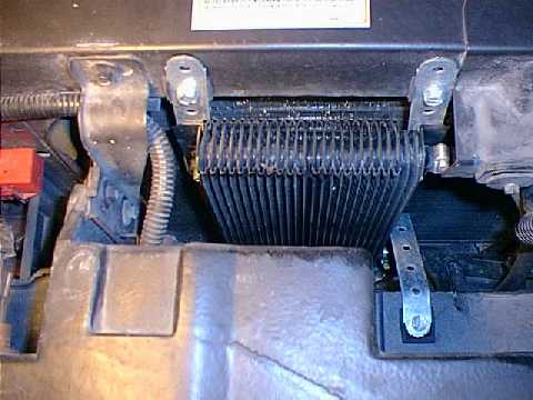
b. The transmission is connected to the radiator using two metal tubes. These tubes start at the passenger's side of the transmission. They cross under the front of the motor and end up on the driver's side of the car. The tubes are connected to the radiator on the left rear surface. The lower tube is directly above the large water hose at the bottom of the radiator. The upper tube is connected to the same radiator surface a foot or two above the lower tube. You will be cutting the tubes just behind the first bend, on the passenger's side when the tubes cross under the front of the motor.
c. Remove the ribbed plastic cover that is protecting the tubes.
d. Remove the two clips that are holding the tubes together.
e. Locate the rubber cooler hose that was supplied with the install kit. And find the plastic bowl to catch tube fluid.
f. Separate the tubes. Apply the mini-tube cutter to one of the tubes and rotate until cut. A small amount of fluid slipping past the cutter may make this job messy. Slip one end of the rubber hose to the transmission side of the tube just cut. Keep the other end higher than the tube.
g. Bend the radiator side of the tube that was just cut over to the fluid catch container.
h. Slip on four hose clamps on the open end of the rubber hose. Remember to keep the open end of the rubber hose higher than the hoses or else you will have a fluid mess on your hands.
i. Position the tube cutter closer to the motor by an inch or too and cut the second tube. The first tube will be longer than the second tube. Slip the other end of the rubber over this end. Bend the radiator side of the tube just cut to the drain bowl.
j. These two connections will have use two hose clamps per tube. Adjust the hose on the shorter cut tube so that the two hose clamps will be separated by about ½ to 3/4th of an inch when tightened down. Insure the clamps are pressing the hose against tubing, not air.
k. Position and tighten two hose clamps on the longer cut tube.
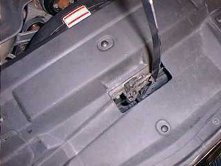
l. Feed the loop of hose between the bumper cover and the sheet metal above the cover. You may want to install an old cut piece of radiator hose to act as a bumper to soften the sharp edge of the sheet metal. Such a bumper is shown below.
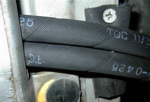
Notice the small sheet metal screw holding the old hose in place under the tubing. I tied both hoses together using tie-wraps. You may want to do this, or re-use the two tubing clips.
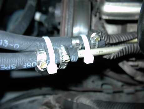
m. Go back up to the top of the engine compartment and position the hose loop to the lower cooler's flared fitting. Cut the rubber hose loop so that the bottom hose is just long enough to slide onto the bottom cooler fitting.
n. Slide hose clamp over the hose and then slide the hose onto the bottom fitting. Tighten this hose clamp.
o. Move the hose to the upper cooler fitting. It should be just long enough to fit. Slip on another hose clamp at this end. Slide the hose on the upper fitting and tighten the hose clamp.
4. Finishing up
a. The radiator cooler should have mostly drained by now. Using a 13mm tubing wrench, disconnect the two radiator tubes from the radiator. You may want to use another wrench to counter-torque the fittings as you remove the tubes.
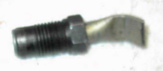
b. Take the tubes to your work bench and cut each fitting off, leaving about an inch and a half of tubing sticking behind the fitting.
c. Using a bench vise, flatten the tube behind the fitting about ½ inch from the end. Bend the flattened tube 45 degrees or so. This will help plug the tube. A prepared tube is shown below.
d. Reinstall the two plugged fittings to plug up the old cooler holes.
e. Maples 8 used two metric bolts to act as plugs. You may want to use Teflon tape on the bolts treads to seal the connection.
f. Pour back in the transmission fluid you collected in your tubing bowl.
g. Re-install the plastic cover and put the hood latch lever back on.
h. Don't forget to check the fluid level after you drive the car enough to warm the transmission up.
i. Once last item - keep an eye on the motor side hose connections. You may find you may need to tighten the four hose clamps after a couple of weeks go by. Especially keep an look out for leaks if you are running a performance chip - transmissions fluid pressure are somewhat higher and a marginally loose clamp will show up under this higher stress.
References:
1. Author's and Editor's personal experience with their Mark VIII .
2. Question and replies on www.markviii.org conference areas.
Submitted by:
Author: Jerry Heep (HOTLNC) jjheep@swbell.net
Technical Editor: Woodie Maples (MAPLES 8) maples@lelindsayconst.com